3D scanning objects for AR
On behalf of a retail client, I’ve been exploring techniques for 3d scanning real-world objects for the purposes of displaying them in AR. In this blog post I am going to go over the full asset creation process from start to finish – outlining how to take an existing physical object and process that into a high-quality and performant 3d asset. While the output of this is easily adaptable to any platform, I’m going to focus on preparing a model specifically targeted for mobile AR by creating a .usdz file compatible with Apple’s recently announced AR Quick Look feature released with ios 12.

To demo this process I captured a very sacred object – ‘Edie’ a ceramic statue of a pig that once belonged to my late grandmother. The main technique I used to capture this object is called photogrammetry. By taking many overlapping pictures of the same object from varying angles, and knowing the characteristics of the camera lens, it’s possible for software to solve how those photos must fit together through detection of similar details in multiple images. From there it can then recreate the geometry and texture of the captured object in 3D.
Step 1: Photography
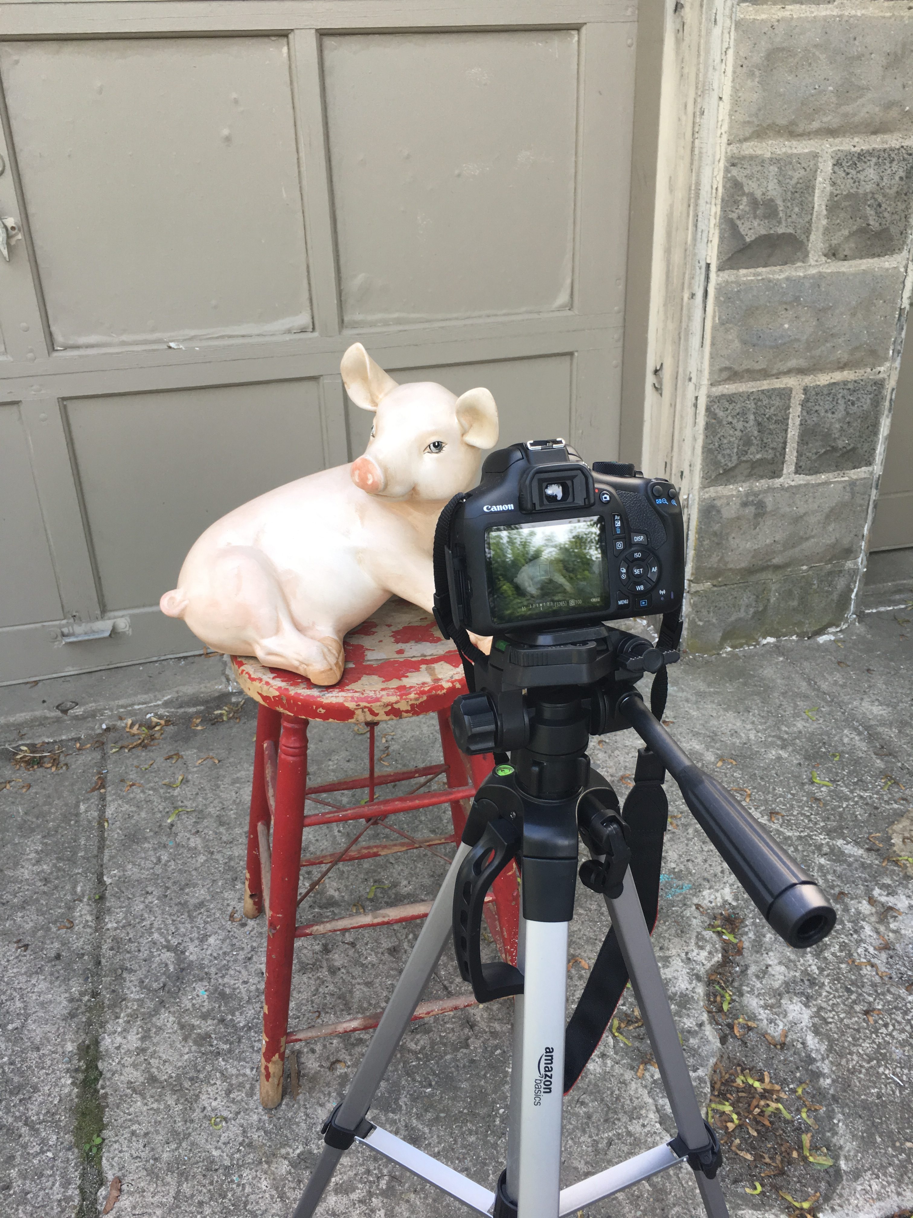 Edie has a slight glossy luster and some challenging areas behind her front legs, but otherwise has an organic shape that lends itself well to photogrammetry. If there were areas of transparency or more highly reflective surfaces then it would be necessary to paint those areas of the object with a washable matting spray. This would allow us to capture the geometry, and the texture would then need to be recreated artificially.
Here is a great rundown on photogrammetry with reflective objects.
In the case of this object, I was able to eliminate most of the reflections by controlling the shooting conditions. Nice diffuse studio lighting with a turntable rig and blank background to shoot against would work best, but I found that I can get great results shooting outside in a shady spot or shooting on an overcast day. Just know that you do not want any change of lighting on your object either from your own shadow or from a shift in cloud cover nor do you want anything moving between captured shots.
This blog post gives a decent rundown on lighting for photogrammetry
I shoot with a Canon EOS Rebel T6. I capture all of my images RAW and at max resolution. Because the software is trying to find identifying points across images it’s very important to capture sharp images with a large depth of field. So I set my iso to 100 to reduce graininess and using a high aperture setting to stop down the lens to keep everything in crisp focus. The last variable is the shutter speed, and I set that appropriately based on my other settings and the lighting conditions. In my experience, this usually requires a tripod to keep the camera still and the images sharp.
With the camera setup, I work around the object moving my camera about every 7 degrees or so between shots. Objects with more concavity and fine details require more shots. I aim for about 50% overlap between each image.
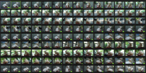
For Edie, I started low and captured one ring of shots and then adjusted my tripod and shot another ring from a higher perspective. I then set up a few overhead shots and details of other occluded areas. I probably shot more than required, and depending upon the software used this can slow down processing.
Step 2: Generating 3D object
There are two popular desktop photogrammetry software packages and a couple of cloud-based subscription services. I used a desktop app called Reality Capture. I chose RC, mainly because the processing time is significantly faster. The other popular option is Agisoft.
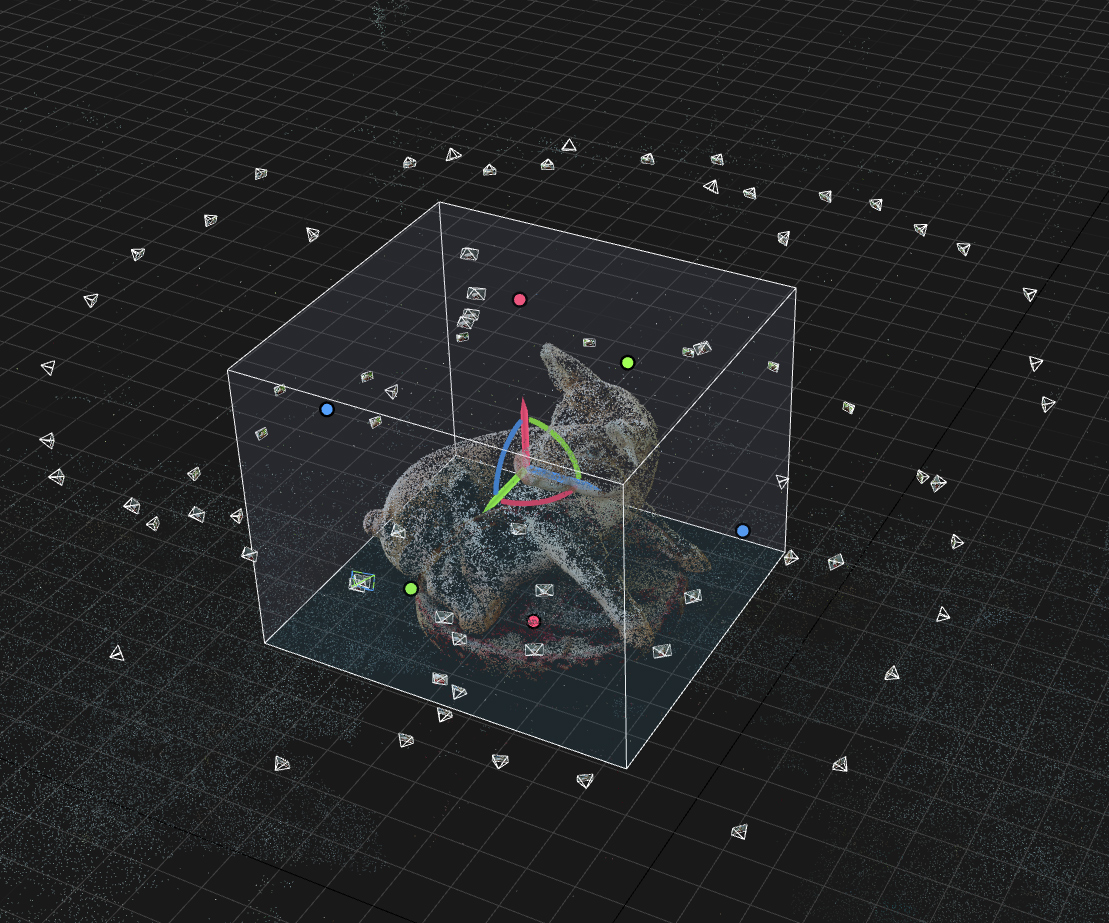 At this point, with a collection of about 80 images, I just imported them directly into RC and began aligning images. This is the process where the software determines how all of the cameras were set up in relation to the object. The output of this step is a sparse point cloud – an initial cluster of points that beings to roughly show the captured geometry. When shooting Edie, I was also capturing other elements in the environment and to save time I use the sparse point cloud as a reference to reduce the active area to just the area that I want to process.
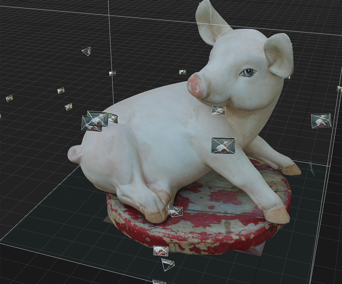 Once I adjusted the capture region the next steps are fairly straightforward for reconstructing the geometry and building the textures. In fact, if you are satisfied with the default settings the entire model reconstruction can be as simple as a single click. After final processing, which took about 15 mins on my GTX 1060 video card, the end results are an extremely high polygon mesh with a photo quality texture.
Step 3: Retopology
Although RC has a suite of tools to simplify, close holes, smooth, delete, and otherwise optimize areas of the mesh my next step is usually to export the model and texture out of RC into zBrush to create optimized UVs and clean topology. I found this step to be frustratingly tricky and I would love to find a simpler way to pull this off, but so far this has been the only way I know that works.
For some use cases the mesh simplification tools in RC are sufficient and if you aren’t animating (deforming) the model or painting additional surface maps then the 3d files produced may be usable as they are. However, while the mesh that RC creates is remarkable in detail, the surface topology is always a mess.
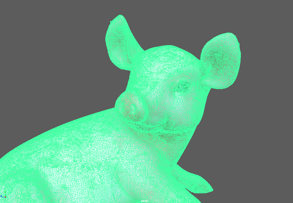
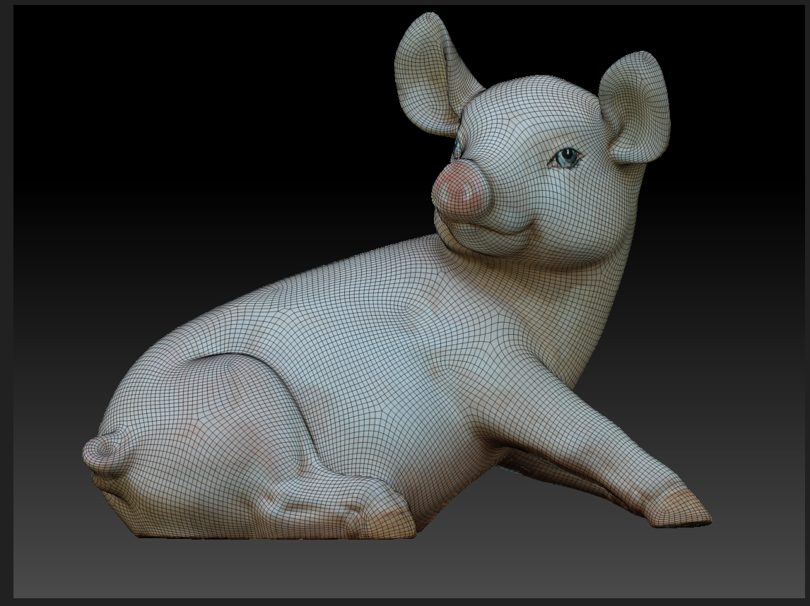
Running the model through Zbrush allows us to leverage its powerful zRemesher tool, but it can be a fussy process because ZRemesher destroys the existing UVS.
The general technique I use is to take the imported mesh, subdivide that into an extremely high poly mesh and then convert it’s texture to polypaint. With polypaint enabled we aren’t wrapping the pixels of texture to the UVS, but rather coloring the actual polygons – hence the need to work with a very dense mesh. I then duplicate that mesh and run that copy through zRemesher to produce the clean well-optimized topology. Again, the problem is that this mesh no longer carries any texture or polypaint information. So the next step is to create uvs with uvMaster plugin and then project the polypaint from the original high poly model on to the optimized model, but there’s still one problem. Because Polypaint is coloring the polygons the density of the newly optimized model is likely insufficient to carry the resolution detail of the original texture.
So, one more step is involved. We have to subdivide our optimized model to create sufficient mesh detail to carry the polypaint projection. Once projected we can then delete the original mesh, convert our polypaint back to a texture and then bring our subdivisions back down. This video gives a great step by step walkthrough.
Step 4: Creating PBR Surface Maps
At this point, we have our original high poly mesh, our newly optimized low poly mesh, and our new albedo, or base color texture all exported from ZBrush. I start a new project in Substance Painter from the low poly mesh using standard PBR Metal Rough configuration. The first step is to bake out the normal map using the high poly mesh along with the other standard base maps. I’ll also go through and clean up any artifacts in the base texture such clone stamping out some of the color defects from occlusions or reflections.
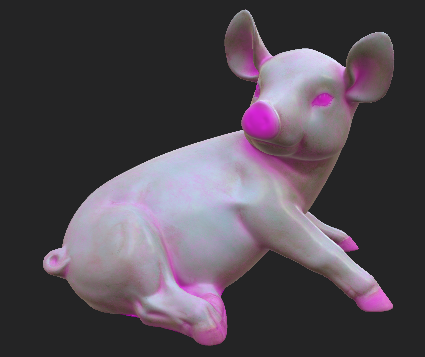
For Edie, the texturing process was actually pretty simple. Because I captured her in the shade, there were no extreme lighting conditions that required de-lighting. Nor did she have a complex surface with varying metallic and roughness that required detailed painting. Mainly she is evenly smooth with a slight glazed specular surface. Her nose, and hoofs were somewhat rougher so I created a fill layer for roughness and masked in those areas by hand along with a subtle dirt generator to add general realism and help collect roughness around concave areas. I finally add in a bit of sharpening and color correction to the base image.
Now the object is finished with clean optimized geometry in our low poly .obj file and a realistic set of surface maps exported out of substance painter. Here is a sample I’ve uploaded to Sketchfab:
Step 5: Converting to .usdz format
The final step is to convert our model and associated textures into the .usdz format to embed on our webpage. This will allow the asset to work with Apple’s QuickLook AR feature .
Quicklook is a mechanism by which users can easily view 3D assets and display them in AR from any mobile Safari browser. With a reported 51% of mobile web traffic coming from Safari and with the rapid adoption rate of new ios versions, Quicklook is a likely to be a great way to deliver high quality and performant AR content to mobile web users in the very near future.
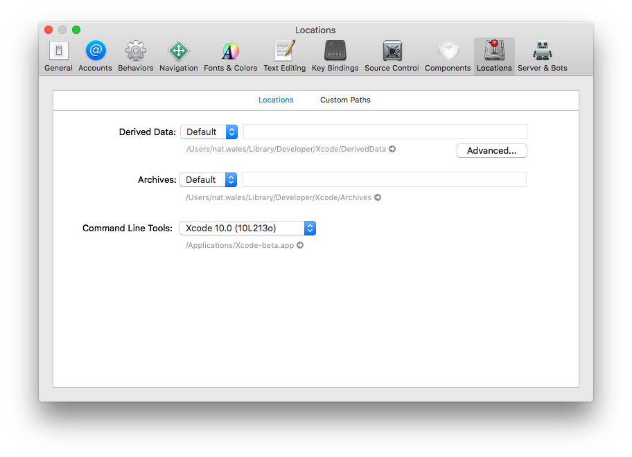
At the time of this post ios12 is still in beta, so you will need an ios developer license to install ios 12 beta on your mobile device as well as XCode 10 beta which includes the usdz encoder as part of its command line tools.
The following code run in the terminal will covert the obj file and the associated surface maps:
xcrun usdz_converter edieThepig3.OBJ EdieThePig.usdz -g piggy -color_map pigLowPoly_defaultMat_AlbedoTransparency.png -metallic_map pigLowPoly_defaultMat_Metallic.png -roughness_map pigLowPoly_defaultMat_Roughness.png -normal_map pigLowPoly_defaultMat_Normal.png
There isn’t anything really tricky here, but pay careful attention to the -g piggy argument. That’s the root mesh group name from the obj file.
This will generate a .usdz file to embed on your website. The embed code itself couldn’t be simpler
<a rel="ar" href="EdieThePig.usdz">
     <img src=EdieThePig.usdz>
</a>